NFPA 86 (Ovens and Furnaces) and NFPA 87 (Fluid Heaters) recognize that some industrial heating systems are installed where electricity is not available, and heaters must be operated without the benefit of a forced-draft, clean-air purge prior to startup.
Nevertheless, natural draft furnaces can be started up safely by ensuring ventilation doors and exhaust ducts are wide open for a sufficient amount of time prior to ignition. Natural draft ventilation is driven by buoyancy forces, just like the chimney effect that occurs when exhaust from a fire rises up a chimney (i.e., because “hot air rises”). The difference with pre-ignition purge is that the buoyancy forces arise from the difference in gas density of methane and air. One thousand liters of air weighs about 1.2 kilograms, whereas one thousand liters of natural gas weighs less than 700 grams. (By comparison, helium and hydrogen are even less dense, but the density of natural gas is sufficiently low to cause a natural draft purge in a reasonable amount of time.)
The purpose of purging a furnace prior to burner light-off is to remove any combustible gases from the furnace enclosure and thereby prevent accidental ignition of an accumulation of gas from a prior unsuccessful light-off or leaking shutoff valve. When forced ventilation is used, the standards require purging the enclosure with 4 volumes of fresh air prior to light-off. In other words, if a furnace enclosure is 100 cubic meters, and the forced draft fan can be proven to deliver at least 100 cubic meters of fresh air per minute, a purge duration of 4 minutes can be programmed into the startup sequence and the code requirement will be satisfied.
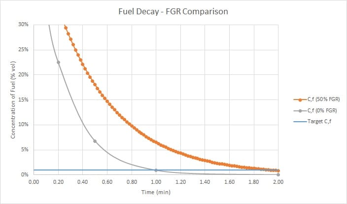
However, when natural draft ventilation is the only available method of purging, determining the length of time for purge is not straightforward. Without a fan, it is more difficult to determine the exhaust gas flow rate, but more importantly, the exhaust flow rate varies with the amount of residual methane still in the furnace. As the furnace becomes more diluted with air (i.e., as the purge process dilutes the initial methane concentration down to lower values) the buoyancy driving force declines, and so does the purge rate. There is no way to ensure a certain number of “fresh air purge volumes” are forced into and out of the enclosure because the volumetric flow rate changes with time.
To overcome this problem, the Section 8.5.1.2 of NFPA 86 requires the purge time to be determined by measurement, at a time when the furnace is at normal ambient temperature. The preferred method of doing so relies on combustible gas analyzers and oxygen analyzers to continuously measure the exhaust flow leaving the furnace until the concentration falls below 25% of the LFL (lower flammability limit) of the fuel gas in air.
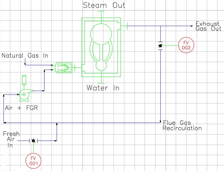
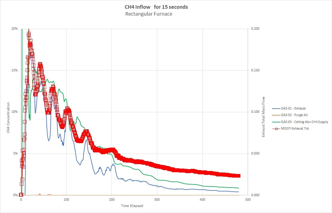
This author has modeled the accumulation and dissipation of natural gas in a hypothetical furnace using a large-eddy-simulation software tool called Pyrosim, which is derived from the NIST code FDS (Fire Dynamics Simulator). A video showing the process for a 20 cubic meter furnace is shown here, and a plot of exhaust concentration versus time for the simulation is also shown.
These results are not applicable to any furnace or gas source or combustion system other than the one modeled, and readers SHOULD NOT extrapolate these results to any other furnace or application. The ventilation rate depends strongly on the size of the openings (for exhaust gas outflow and fresh air inflow) and the time required to purge an actual furnace in the field could vary greatly from case to case. Furnace users are urged to consult with a purge specialist to determine the correct purge time for their own applications.
The purpose of “Investigation Anecdotes” is to inform our readers about the intriguing field of engineering investigations. We hope you are instructed by this content, and we encourage you to contact us if you seek additional information.