Category Archives: Explosions

Investigations of explosions including dust and vapor deflagrations, detonations, bleves, vessel ruptures, whether confined or congested.

Propane Valve Malfunction Examples

For approximately twenty years, home-use propane cylinders have been equipped with valves that contain six very important safety features:

1. Gas service valve to manually open and close the flow path from cylinder to appliance.
2. Pressure relief valve which vents a small amount of gaseous propane if the internal cylinder pressure exceeds a safe value (to prevent catastrophic cylinder rupture).
3. Bleeder valve (+ dip tube) to provide visual indication (white mist) during filling when liquid propane level inside the cylinder reaches its safe upper limit (i.e., overfilling is imminent).
4. Overfill protection device (OPD) which functions to halt liquid inflow to a cylinder when liquid propane level inside the cylinder reaches its safe upper limit.
5. Automatic shutoff valve which prevents gas flow out of the cylinder when the hose to the appliance is not fully connected to the cylinder nozzle.
6. Excess flow valve which halts propane flow out of the cylinder when the flow rate is excessive (e.g., after a catastrophic hose failure).
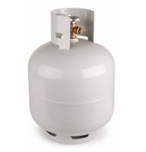
This author has investigated multiple cases where propane releases and flash fires were caused when the safeguards failed to function as they were intended.

The underlying hazards that create the need for the safeguards are:
1. Gas service valve. The user should be able to exercise control over the flow of propane to the appliance.
2. Pressure relief valve. The cylinder may be subjected to excessive internal pressure for either of two reasons: (a) if the cylinder is overfilled at room temperature and is later exposed to mildly higher temperatures (+25 degrees F or higher), the propane liquid can expand and create unsafe internal pressures; or (b) if the cylinder is filled to a safe level (i.e., approximately 20% vapor space above the liquid) and is later subjected to excessive heating from a fire, the liquid+vapor mixture can reach an unsafe pressure. In either case, the pressure relief valve’s job is to reduce the internal pressure by venting a small amount of the propane vapor until the internal pressure declines to a safer level. This safeguard helps prevent internal pressures that can cause the cylinder to rupture catastrophically.
3. Bleeder valve (+ dip tube). The bleeder valve and dip tube help the filling attendant visibly see when the liquid propane level in the cylinder has reached its maximum safe level (see 2 above). When the tiny stream of propane exiting the bleeder valve during filling changes from transparent vapor to a white mist, the maximum safe liquid level has been reached and the attendant is warned to stop the filling operation immediately.
4. Overfill protection device (OPD). The OPD is an automatically-actuated valve that is intended to achieve the same outcome as the bleeder valve (i.e., prevention of overfilling the cylinder with liquid), albeit without human intervention. The OPD comprises a toilet-tank style float inside the cylinder that closes off the flow path for liquid to enter the cylinder from the filling pump when the desired safe liquid level (see 2 above) has been reached.
5. Automatic shutoff valve. The Automatic shutoff valve (ASV) is a poppet-style valve that is intended to prevent the flow of propane vapor out of the cylinder until the connector nut has been fully tightened to a gas-tight sealing condition. In principle, an engagement tab inside the connector doesn’t engage the ASV’s spring-loaded isolation component until a satisfactory seal is made between the cylinder nozzle and the threaded connector nut. This is a feature that prevents gas flow out of the cylinder if the service valve is accidentally opened during storage or at any time before the appliance connection is made.
6. Excess flow valve. The Excess flow valve prevents or minimizes propane flow under circumstances where the connector is properly sealed but a downstream component (e.g., hose) fails in a way that fuel may be released to the environment instead of the appliance burner. The feature that carries out this function is a spring-loaded sphere that is normally positioned to permit a normal flow of propane vapor but is relocated to a position where the flow orifice is obstructed by the sphere when the drag force on the sphere exceeds the spring force (i.e., when flow velocity is high).

The subject safeguards (applicable to 20 lb propane cylinders) are described and specified in the CGA V-1 document “Standard for Compressed Gas Cylinder Valve Outlet and Inlet Connections”, specifically under connection style CGA 791.

While there is no doubt that the CGA 791 design has prevented numerous propane releases and injuries since it was first promulgated in 2000, this investigator believes it is inferior in one important way to the CGA 600 design that is currently approved only for small (1 lb) propane cylinders. The inferior feature involves the sealing geometry (radial versus axial) in the two designs, and the 791 design inherently provides a lower level of sealing certainty than the 600 design.

This investigator has opined that the 791 design’s inferior feature constitutes a safety defect if the resultant sealing inadequacy leads to a dangerous release of propane that causes personal injury or property damage.

The purpose of “Investigation Anecdotes” is to inform our readers about the intriguing field of engineering investigations. We hope you are instructed by this content, and we encourage you to contact us if you seek additional information.
 

Code Violation Causes Explosion

The California Mechanical Code (CMC) is one of thirteen parts of the California Building Standards Code that is adopted into law every three years by the California Legislature. The other 49 U.S. states adopt similar safety codes, which generally include the following titles (preceded by ): Building Code, Electrical Code, Fire Code, Mechanical Code, Plumbing Code, Residential Code, etc.

One of the primary objectives of the mechanical code is to help ensure that heating, ventilating, and air conditioning equipment installed in buildings are designed, operated, and maintained safely. Many HVAC systems utilize natural gas, which is highly flammable and can cause explosions.
This author investigated a natural gas explosion (also called deflagration, or subsonic combustion wave) that was caused by a series of maintenance errors, a heater malfunction, and a major code violation.

The maintenance errors caused natural gas to be released into a heater room, the code violation permitted the natural gas to accumulate in the room instead of being safely vented outdoors, and the malfunction permitted the heater to re-start automatically in an unsafe state, which ignited the explosion. Two workers received serious burn injuries from the incident, but the explosion wasn’t strong enough to damage the building.

It was difficult to rank the errors and defects according to their level of egregiousness, but the worst one was undoubtedly the combined design defect and construction defect associated with the building that housed the gas-fired heater. The heater was located at ground level inside a 23-foot tall enclosure construction from concrete masonry units (i.e., cinder blocks). The architect was responsible for the defective design, which contemplated heating equipment inside the room but didn’t incorporate the code-required ventilation area. The general contractor and appliance installer were responsible for allowing the heating equipment to be installed in the room without the proper ventilation.

The CMC requires ventilation at the top of any enclosure that houses gas-fueled appliances. The purpose is to vent natural gas (which is lighter than air) in the event of a substantial release of gas into the indoor space. Allowing flammable gas to accumulate in an enclosure is the first step in the process of forming an explosive device that lacks only an ignition source to turn into a horrific fireball or a destructive blast wave. The subject room was well sealed along the upper 75% of its height but was equipped with a louvered door at the bottom that effectively allowed combustion air into the room to supply oxygen for the heating appliance. Combustion products from the heater were vented directly to the outdoors by an electric blower, and the replacement air entered through the door louvers.

When the gas pipe developed a leak (the facts weren’t entirely clear about the size of the leak was or how it began), the gas rose to the ceiling and accumulated there, displacing the air below it to the outside environment through the door louvers.

This author performed a Large Eddy Simulation (LES) of the gas accumulation phase which showed the steady-state fuel gas concentration in the upper three-quarters of the room to be substantially greater than the Upper Flammable Limit for natural gas (approximately 15 percent by volume). This fact turned out to be the sole reason the building didn’t explode – a large fraction of the fuel gas present in the room had accumulated in zones that were too rich to burn (not enough oxygen present).
Nevertheless, when the employees were instructed to enter the room and shut off the gas to the heater, their motion created a flammable zone in some portion of the lower 25% of the room’s volume. When the defective heater ignited the flammable mixture as they were exiting the room, the fireball that was created pushed flames out through the open door and burned them badly as they tried to escape. Thankfully both survived.

Posted below are two videos showing the LES simulations for Case 1 – as installed without any venting at the ceiling, and Case 2 – as required by code, with a code-compliant opening of only 150 square inches of flow area at the top of the heater room. Case 1 shows high gas concentration (red) from ceiling down to the top louver of the entry door when gas is flowing and no significant dissipation after the gas source is shut off. Case 2 shows a temporary accumulation of moderate gas concentration (green) until the gas source is shut off, after which full dissipation occurs through the upper vent. The simulation runs approximately 24x faster than real time.

This gas accumulation simulation (along with testing of the defective heater, timeline analysis of witness testimony, and plumber standard of care analyses) helped the parties reach a resolution in this case.


Purging Natural Draft Furnaces

NFPA 86 (Ovens and Furnaces) and NFPA 87 (Fluid Heaters) recognize that some industrial heating systems are installed where electricity is not available, and heaters must be operated without the benefit of a forced-draft, clean-air purge prior to startup.

Nevertheless, natural draft furnaces can be started up safely by ensuring ventilation doors and exhaust ducts are wide open for a sufficient amount of time prior to ignition. Natural draft ventilation is driven by buoyancy forces, just like the chimney effect that occurs when exhaust from a fire rises up a chimney (i.e., because “hot air rises”). The difference with pre-ignition purge is that the buoyancy forces arise from the difference in gas density of methane and air. One thousand liters of air weighs about 1.2 kilograms, whereas one thousand liters of natural gas weighs less than 700 grams. (By comparison, helium and hydrogen are even less dense, but the density of natural gas is sufficiently low to cause a natural draft purge in a reasonable amount of time.)

The purpose of purging a furnace prior to burner light-off is to remove any combustible gases from the furnace enclosure and thereby prevent accidental ignition of an accumulation of gas from a prior unsuccessful light-off or leaking shutoff valve. When forced ventilation is used, the standards require purging the enclosure with 4 volumes of fresh air prior to light-off. In other words, if a furnace enclosure is 100 cubic meters, and the forced draft fan can be proven to deliver at least 100 cubic meters of fresh air per minute, a purge duration of 4 minutes can be programmed into the startup sequence and the code requirement will be satisfied.

However, when natural draft ventilation is the only available method of purging, determining the length of time for purge is not straightforward. Without a fan, it is more difficult to determine the exhaust gas flow rate, but more importantly, the exhaust flow rate varies with the amount of residual methane still in the furnace. As the furnace becomes more diluted with air (i.e., as the purge process dilutes the initial methane concentration down to lower values) the buoyancy driving force declines, and so does the purge rate. There is no way to ensure a certain number of “fresh air purge volumes” are forced into and out of the enclosure because the volumetric flow rate changes with time.

To overcome this problem, the Section 8.5.1.2 of NFPA 86 requires the purge time to be determined by measurement, at a time when the furnace is at normal ambient temperature. The preferred method of doing so relies on combustible gas analyzers and oxygen analyzers to continuously measure the exhaust flow leaving the furnace until the concentration falls below 25% of the LFL (lower flammability limit) of the fuel gas in air.

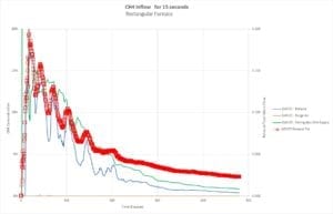
This author has modeled the accumulation and dissipation of natural gas in a hypothetical furnace using a large-eddy-simulation software tool called Pyrosim, which is derived from the NIST code FDS (Fire Dynamics Simulator). A video showing the process for a 20 cubic meter furnace is shown here, and a plot of exhaust concentration versus time for the simulation is also shown.

Plot of CH4 concentration during natural draft purge

These results are not applicable to any furnace or gas source or combustion system other than the one modeled, and readers SHOULD NOT extrapolate these results to any other furnace or application. The ventilation rate depends strongly on the size of the openings (for exhaust gas outflow and fresh air inflow) and the time required to purge an actual furnace in the field could vary greatly from case to case. Furnace users are urged to consult with a purge specialist to determine the correct purge time for their own applications.

The purpose of “Investigation Anecdotes” is to inform our readers about the intriguing field of engineering investigations. We hope you are instructed by this content, and we encourage you to contact us if you seek additional information.
 

Boiler Purge Causes Explosion

During a recent explosion investigation, this author discovered a new failure mode that is not sufficiently addressed in NFPA’s trio of industrial heating equipment standards (NFPA 85, NFPA 86, and NFPA 87) that cover Boilers, Ovens, and Fluid Heaters, respectively. The failure mode occurs only in heating systems equipped with natural gas burners and flue gas recirculation (FGR) for control of NOx emissions. The investigation where the failure mode manifested itself happened to be concerned with a boiler explosion, but ovens, furnaces, and fluid heaters are equally capable of experiencing the same problem, if certain factors are in play.
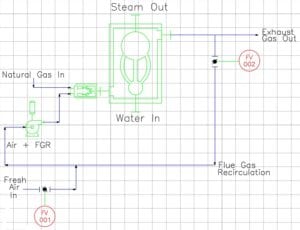
The schematic below identifies the primary equipment that plays a role in the incident scenario. In addition to the boiler, burner, blower and natural gas source, there are two flow valves (FV-001 and FV-002) that control the amount of FGR blended with fresh air that enters the burner. On smaller boilers, FV-001 is set manually during commissioning to approximately 50% open and rarely changed, whereas FV-002 is typically an automatic valve with two discrete positions – closed (no recirculation) and normal (standard recirculation).

Schematic of Boiler with FGR

NFPA burner safety requirements require a pre-ignition purge at the beginning of each burner startup to help ensure the combustion chamber is free of residual fuel gas or any other combustible vapor. NFPA burner standards have included a purge requirement for at least 50 years and such requirements have reduced the rate of explosions significantly.
The goal of the purge cycle is for approximately 4 volumes of fresh air to be admitted into the combustion chamber to drive out any unwanted combustible gas or vapor. For example, if the combustion chamber has a volume (𝑉 = 100 ft3) and the blower is delivering a flow rate Vdot = 400 acfm the purge time should be 𝑡 =1.0 min. This amount of purge is almost always conservative enough to ensure combustible vapors are diluted to a nonflammable concentration in the firebox. The very first volume of fresh air purge in theory is enough to remove the combustible vapors if a plug flow model is assumed for the air flow inside the chamber. The requirement for 4 purge volumes arises from the fact that the plug flow model isn’t conservative enough if plug flow behavior is not achieved. Hence, a perfectly-stirred vessel model is used instead. The decay of fuel concentration in the firebox is exponential with time, and 4 volumes of purge air will take a 50% fuel concentration down to 1%.
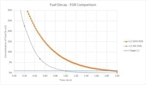
However, if the purge air isn’t comprised of pure air, but rather a mixture of “flue” gas with a high concentration of unburned fuel from the prior unsuccessful burner ignition attempt, the purging process is much slower. The figure below shows the difference in decay rates between the normal case, where the purge air is 100% air, and the compromised case, where the purge air comprises 50% FGR (with residual fuel) and 50% fresh air. When purge is carried out with contaminated air, the number of purge volumes required is 8, not 4.
PSR decay rate with contamination in purge air

For the boiler explosion case described above, this author found that FV02 had been unplugged from its power source and the damper was stuck in a partially open condition. After 3 unsuccessful ignition trials in rapid succession, the spark igniter set off an internal deflagration that damaged the vessel walls such that a complete replacement of the boiler was required.


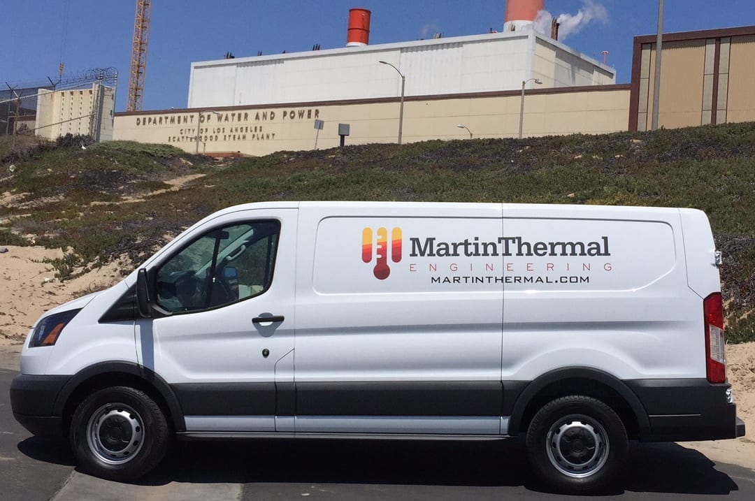
Mobile Investigation Workshop

The author of this blog is pleased to announce that a new Mobile Investigation Workshop has been added to the Martin Thermal Engineering collection of tools.

The workshop is equipped with many types of hand and power tools for disassembling products and extracting evidence from a fire scene, as well as instruments that are vital to the conduct of appliance tests and exemplar examinations, including thermocouples, pressure gauges, and flow meters. Multiple video cameras with tripods can be deployed to monitor and record mechanical meters (e.g. gas volume).

We can also extract samples of automotive fluids and combustion gases for submission to an analytical lab for chemical characterization. Evidence chain of custody paperwork is maintained in a folder on board. Marking and labeling tags and signs can be employed when multiple pieces of evidence require identification.

ScattergoodMTEtransitvan

A battery charging station, complete with inverter is soon to be installed, which will make the mobile workshop self-sustaining for multi-day inspections.

The purpose of “Investigation Anecdotes” is to inform our readers about the intriguing field of engineering investigations. We hope you are instructed by this content, and we encourage you to contact us if you seek additional information.
 

Portable Cookstove Defects

Portable cookstoves are used by caterers and campers to bring the convenience of a “kitchen appliance” to places where such appliances are normally not available. Some cookstoves are fueled with liquefied propane that is supplied in 1-lb canisters (first photo) or 20-lb containers (second photo). Others utilize liquefied butane that is supplied in aerosol-like cans (third photo). While all these systems are equipped with unique safeguards, certain types have failed catastrophically, injuring workers and guests.

Cookstove Safeguards. Butane cookstoves (example in fourth photo) are generally equipped with a multi-function gas safety valve. When the fuel can is installed, a lever must be pressed to latch the can into place so that the gas will begin flowing through the valve to the burner. The valve also has a pressure-safety pin that is designed to trip the latch and disengage the can when the fuel pressure exceeds a safety threshold. However, in some models, the retracting mechanism has been observed to fail intermittently and the can fails to disengage even though the pressure-safety pin performed as it should.

Can Safeguards. Small butane fuel cans are also equipped with certain safety features that are designed to prevent or mitigate catastrophic releases of flammable gas. Because the fuel cans are installed horizontally into the cook-stove chassis, the fuel withdrawal tube is equipped with a right-angle extension to ensure that butane vapor is withdrawn from the headspace, rather than butane liquid from the lower portion of the can. The neck of the can contains a feature that is intended to prevent improper rotation in the stove, but users can unknowingly defeat this safeguard and install the can in the wrong orientation, permitting butane liquid to be withdrawn instead of butane vapor, which is undesirable.

This author has investigated several flash fires involving portable cookstoves and has identified product defects as well as certain ways the products can be misused. In the worst-case scenario, the fuel canister overheats and ruptures, releasing a fireball that causes personal injury and property damage.

The purpose of “Investigation Anecdotes” is to inform our readers about the intriguing field of engineering investigations. We hope you are instructed by this content, and we encourage you to contact us if you seek additional information. Copyright Martin Thermal Engineering, Inc. (2013)


Exploding Chicken Soup

Most people know that water boils at 212°F (100°C) at sea level. They also know that if the pot is open (i.e., not a pressure cooker), the bubbling, steam-water mixture will not exceed 212°F. While this observation is generally true, there is another aspect of boiling that many people are not familiar with – “superheating”. In order to form a steam bubble in a pool of liquid water, the water temperature must actually exceed 212°F in a thin film near the heated pot bottom. This “superheating” phenomenon is usually limited to a few degrees at most, and generally diminishes to 0.1°F or less when vigorous boiling begins.

This superheating is the driving force for the rapid phase-change that is called boiling. Without excess thermal energy available in the liquid molecules, their conversion to gas is a slow process – evaporation. Evaporation occurs only at the upper surface of a hot liquid when individual molecules are sufficiently energetic to break the weak intermolecular bonds they share with their neighbors and travel into the air space above.

In contrast, bubble formation involves a huge number of molecules simultaneously. Because of the excess energy of the molecules in the superheated film near the heated pot bottom, they can expand and change phase (from liquid to gas) very rapidly. Thus, the rate of vapor formation in bubbles is many times higher than the rate of vapor formation by evaporation alone. When the vigorous motion of the rising bubbles begins, the superheated liquid in the film and the balance of the 212°F liquid above it in the pot are very effectively stirred together and we measure an average temperature of 212°F essentially everywhere in the pot.

By contrast, when a container of water is heated in a microwave oven instead of through the wall of a pot, bubble formation in the film next to the pot bottom does not occur. Accordingly, dangerous amounts of energy can be deposited into the interior of the water mass creating a large body of superheated liquid water. If superheated liquid water accumulates in the vessel, it can expand explosively when a “nucleation site” (e.g., a fork or dry food particle) makes contact with the energetic liquid.

This author investigated one such injury-causing explosion involving an 8-cup container of homemade chicken soup heated in a microwave oven. Unfortunately, the water was heated about twice as long as it should have been, and it vaporized explosively when a fork was inserted, scalding the woman who was simply trying to spear a piece of chicken. Recommendation: Don’t heat water for long periods of time in a microwave oven and do check it frequently to be sure it doesn’t approach the boiling temperature.

The purpose of “Investigation Anecdotes” is to inform our readers about the intriguing field of engineering investigations. We hope you are instructed by this content, and we encourage you to contact us if you seek additional information. Copyright Martin Thermal Engineering, Inc. (2013)